PART 4 of How to replace damaged bearings on a precision CNC spindle
This is the fourth in a five part series of tips and suggestions for replacing bearing in a precision CNC spindle. This series is specifically for the DIY person with limited resources. It is not a comprehensive description of how a fully equipped shop that specialized in spindle repair works. While we will reference certain specific spindle makes it is primarily intended to be rather generic. If you have a specific question please send an email at [email protected] or call 1-603-483-0333.
In the previous three blogs we considered some tips on getting your spindle apart. We also considered some points concerning Angular Contact Bearings, lubrication and how to preload them. This week we’ll discuss Cylindrical Roller Bearings.
ABOUT CYLINDRICAL ROLLER BEARINGS
Cylindrical Roller Bearings (CRB) offer tremendous radial load capacity. But as noted in an earlier blog they do not have any axial load capacity. For that reason roller bearings are always found with at least one pair of angular contact bearings to provide thrust capacity.
They come in several configurations. The most common types found in spindles include the following:
- Straight Bore
- Taper Bore
- Single Row
- Double Row
- Special
- Machined Lubrication Groves
Let’s take a look at a typical CRB. The illustration is a double row tapered roller. It has optional machined oil grove and penetrations in the outer race. Note that the rollers are held in place on the inner race with the cage material. But the outer race is free to slide off and hence has no axial thrust capacity.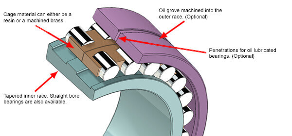
Setting Preload on a Roller Bearing

Roller bearing preload is set radially
As noted in a previous blog angular contact bearings are preloaded in the axial direction. Cylindrical roller bearings on the other hand are preloaded in the radial direction. The method of setting preload varies significantly depending if the bearing is a straight bore or a tapered bore roller. Setting proper preload on a tapered roller bearing is rather straight forward. It is substantially more difficult on a straight bore bearing and we will only speak about it briefly in this blog.
Straight Bore Cylindrical Roller Bearings
Achieving proper preload on a straight bore roller is a matter of shaft and housing fit. So as with ACB bearings we start by looking at the box. Each super precision CRB comes with a data sheet printed on the outside of the box specifying deviation from nominal race dimensions and internal clearance. (All dimensions are in microns) Let’s consider an example where the OD is +1, the bore diameter +6 and internal clearance is 20. To achieve preload in this example the shaft journal will need to be oversize enough to expand the inner race by more than 27µm. This will take up the internal clearance and force the rollers to contact the outer race. For this example if the shaft is not at least at a +27 it will require GPG and be beyond the capability of the DIYer.
The housing bore also comes into play and affects the radial preload. Because CRBs are used to handle radial loads the housing journal dimension is critical for proper spindle performance.
Tapered Bore Cylindrical Roller Bearings
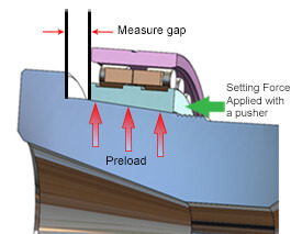
Proper preload on a tapered bore CRB is a matter of adjusting the axial position of the inner race. To start you will need a “pusher”. That is something to push the inner race down over the shaft. At HST we have specially machined heavy pushers that allow us to press evenly on the race. It is possible to tap the race down using a brass rod and tap all around the circumference little by little.
As the bearing is pushed down over the shaft taper it expands the inner race. While making the axial adjustment keep checking the preload. Rotate the outer race after each adjustment and watch the rollers. Every roller (both sets in the case of a double roller) must rotate in sync with the movement of the outer race. There should only be a slight resistance to rotation when all of the rollers are turning in sync with the outer race.
Once that is achieved measure the distance between the inner race and the associated shoulder. Then adjust the spacer accordingly. If the spacer is too small HST will make a new one. However, the DYIer may just add a shim to get oversize and then grind the spacer so the shim plus spacer is at the exact size.
Setting Preload on a Tapered Roller Bearing
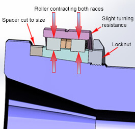
Once Preload is Set Install Spacer & Locknut
This illustrates how the inner race of a CRB expands as axial adjustment is made. The race expands as it is forced further onto the taper angle taking up all of the internal clearances. Once all rollers contact both races the outer race should have a slight resistance to rotation. If it is too stiff the bearing will generate excessive heat and fail prematurely. Also if it is a double row bearing both sets of rollers need to make contact evenly. Once this is set, the gap between the associated shoulder and the inner race must be carefully measured. Make sure that the gap is the same dimension all around and the inner race is not cocked. Then adjust the spacer to this size. Remove the bearing and install the spacer. When the bearing is reassembled the locknut will force the inner race hard against the spacer.
This procedure can be used for tapered roller bearing on either the front or the back of the spindle and is good for both lathe and mill spindles.
Mori Seiki and DMG Mori spindles use a taper bore cylindrical roller up front on many of their mill spindles. The roller is used in conjunction with two angular contact bearings arranged back to back. They will often have another CRB in the tail end of the spindle.
This illustration is a typical mill spindle bearing arrangement that uses a cylindrical roller bearing as the number one bearing and in fact is very similar to many Mori Seiki spindle arrangements. Note that preload is set on the shaft by adjusting the yellow colored spacers. The other spacer sets between the ACBs should be match ground from the factory and not need adjustment (we always check anyway).
Because the ACBs are mounted back to back they will be preloaded when the locknut is set.
Once adjusted the front bearing stack remains on the shaft and the whole assembly is loaded into the housing. The rear roller needs to be removed for installation into the housing.
The arrangement illustrated above provides a very stout and robust spindle. It is also very similar to what we see on Mori and other lathe spindles. One word of caution: many higher end spindles use a hydraulic nut in conjunction with a locknut to maintain preload on the front bearings. Check your machine drawings. If your spindle has a hydraulic nut consider sending it to a qualified repair shop.
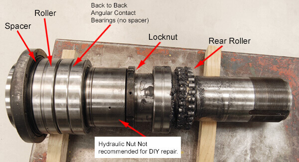
A Mori Seiki SL25 Lathe spindle on its way to disassemble.
This Mori Seiki SL25 lathe spindle uses a roller for the #1 bearing and two ACBs mounted directly back to back to handle thrust. This design uses a hydraulic nut to maintain bearing preload. The lock nut is just for back-up. To remove these bearings requires pressurizing the hydraulic nut to about 10,000 PSI. DO NOT PRESS THESE OFF.
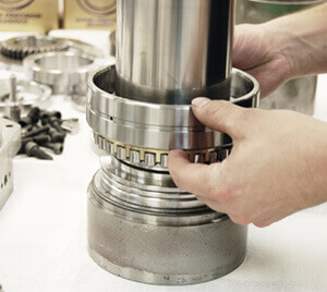
Checking preload on a double cylindrical roller bearing.
When preload is properly set all rollers (both rows) will contact the outer race and there will be a slight resistance to rotation.
The housing ID should be sized to ensure that the roller bearing transfers all radial loading.
Let’s take a look inside the front bearing stack of a typical roller bearing assembly. 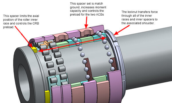
When a bearing stack employs a roller bearing / angular contact bearing combination it is important that the two different types of bearings work independently. That is the roller bearing must handle all of the radial load and the ACBs only handle axial load. There are two different and effective ways to ensure this. One way is to select ACBs that have an OD dimensional deviation of minus 20 – 30 µm. Some bearing houses will help you select undersized bearings. Being undersized guarantees that the ACBs will not support any radial loading.
But those undersized bearings might not be necessary. Check your housing bore. Some manufacturers open up the housing bore past the CRB journal and relieve the area where the ACBs reside. This is very effective in making certain that the roller bearing handles all of the radial load.
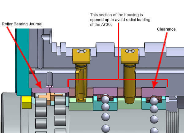
CRBs and ACB must work independently. In this type of arrangement the CRB bearing handles the radial load and the ACBs only handle axial forces.
In many rebuilds the front bearing stack is assembled on the shaft. The preload is set on the shaft. Once the front stack is complete the whole assembly is loaded into the housing. We normally heat the housing up with a heat gun to expand the housing journals. This allows for an easy assembly and avoids transferring forces through the rolling elements.
Take aways:
- Roller Bearings must be used in conjunction with Angular Contact Bearings
- Roller Bearing preload is set by expanding the inner race
- Tapered bore roller bearing preload is controlled by the spacer in between the inner race and the associated shoulder.
- When combined with Angular Contact Bearings make sure only the roller bearing handles the radial loads.
Please send us your comments, suggestions our questions [email protected]
Or call 1-603-483-0333
Next week we’ll talk about some things you may run into such as hydraulic nuts and modified bearings..
PART 4 of How to replace damaged bearings on a precision CNC spindle
This is the fourth in a five part series of tips and suggestions for replacing bearing in a precision CNC spindle. This series is specifically for the DIY person with limited resources. It is not a comprehensive description of how a fully equipped shop that specialized in spindle repair works. While we will reference certain specific spindle makes it is primarily intended to be rather generic. If you have a specific question please send an email at [email protected] or call 1-603-483-0333.
In the previous three blogs we considered some tips on getting your spindle apart. We also considered some points concerning Angular Contact Bearings, lubrication and how to preload them. This week we’ll discuss Cylindrical Roller Bearings.
ABOUT CYLINDRICAL ROLLER BEARINGS
Cylindrical Roller Bearings (CRB) offer tremendous radial load capacity. But as noted in an earlier blog they do not have any axial load capacity. For that reason roller bearings are always found with at least one pair of angular contact bearings to provide thrust capacity.
They come in several configurations. The most common types found in spindles include the following:
- Straight Bore
- Taper Bore
- Single Row
- Double Row
- Special
- Machined Lubrication Groves
Let’s take a look at a typical CRB. The illustration is a double row tapered roller. It has optional machined oil grove and penetrations in the outer race. Note that the rollers are held in place on the inner race with the cage material. But the outer race is free to slide off and hence has no axial thrust capacity.
Setting Preload on a Roller Bearing
Roller bearing preload is set radially
As noted in a previous blog angular contact bearings are preloaded in the axial direction. Cylindrical roller bearings on the other hand are preloaded in the radial direction. The method of setting preload varies significantly depending if the bearing is a straight bore or a tapered bore roller. Setting proper preload on a tapered roller bearing is rather straight forward. It is substantially more difficult on a straight bore bearing and we will only speak about it briefly in this blog.
Straight Bore Cylindrical Roller Bearings
Achieving proper preload on a straight bore roller is a matter of shaft and housing fit. So as with ACB bearings we start by looking at the box. Each super precision CRB comes with a data sheet printed on the outside of the box specifying deviation from nominal race dimensions and internal clearance. (All dimensions are in microns) Let’s consider an example where the OD is +1, the bore diameter +6 and internal clearance is 20. To achieve preload in this example the shaft journal will need to be oversize enough to expand the inner race by more than 27µm. This will take up the internal clearance and force the rollers to contact the outer race. For this example if the shaft is not at least at a +27 it will require GPG and be beyond the capability of the DIYer.
The housing bore also comes into play and affects the radial preload. Because CRBs are used to handle radial loads the housing journal dimension is critical for proper spindle performance.
Tapered Bore Cylindrical Roller Bearings
Proper preload on a tapered bore CRB is a matter of adjusting the axial position of the inner race. To start you will need a “pusher”. That is something to push the inner race down over the shaft. At HST we have specially machined heavy pushers that allow us to press evenly on the race. It is possible to tap the race down using a brass rod and tap all around the circumference little by little.
As the bearing is pushed down over the shaft taper it expands the inner race. While making the axial adjustment keep checking the preload. Rotate the outer race after each adjustment and watch the rollers. Every roller (both sets in the case of a double roller) must rotate in sync with the movement of the outer race. There should only be a slight resistance to rotation when all of the rollers are turning in sync with the outer race.
Once that is achieved measure the distance between the inner race and the associated shoulder. Then adjust the spacer accordingly. If the spacer is too small HST will make a new one. However, the DYIer may just add a shim to get oversize and then grind the spacer so the shim plus spacer is at the exact size.
Setting Preload on a Tapered Roller Bearing
Once Preload is Set Install Spacer & Locknut
This illustrates how the inner race of a CRB expands as axial adjustment is made. The race expands as it is forced further onto the taper angle taking up all of the internal clearances. Once all rollers contact both races the outer race should have a slight resistance to rotation. If it is too stiff the bearing will generate excessive heat and fail prematurely. Also if it is a double row bearing both sets of rollers need to make contact evenly. Once this is set, the gap between the associated shoulder and the inner race must be carefully measured. Make sure that the gap is the same dimension all around and the inner race is not cocked. Then adjust the spacer to this size. Remove the bearing and install the spacer. When the bearing is reassembled the locknut will force the inner race hard against the spacer.
This procedure can be used for tapered roller bearing on either the front or the back of the spindle and is good for both lathe and mill spindles.
Mori Seiki and DMG Mori spindles use a taper bore cylindrical roller up front on many of their mill spindles. The roller is used in conjunction with two angular contact bearings arranged back to back. They will often have another CRB in the tail end of the spindle.
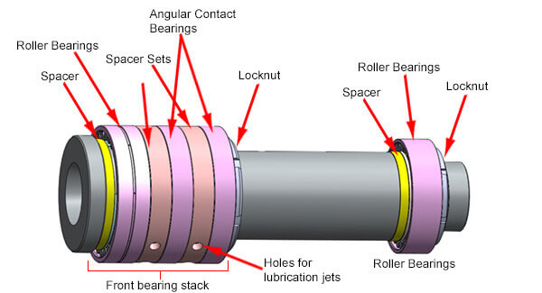
This illustration is a typical mill spindle bearing arrangement that uses a cylindrical roller bearing as the number one bearing and in fact is very similar to many Mori Seiki spindle arrangements. Note that preload is set on the shaft by adjusting the yellow colored spacers. The other spacer sets between the ACBs should be match ground from the factory and not need adjustment (we always check anyway).
Because the ACBs are mounted back to back they will be preloaded when the locknut is set.
Once adjusted the front bearing stack remains on the shaft and the whole assembly is loaded into the housing. The rear roller needs to be removed for installation into the housing.
The arrangement illustrated above provides a very stout and robust spindle. It is also very similar to what we see on Mori and other lathe spindles. One word of caution: many higher end spindles use a hydraulic nut in conjunction with a locknut to maintain preload on the front bearings. Check your machine drawings. If your spindle has a hydraulic nut consider sending it to a qualified repair shop.
A Mori Seiki SL25 Lathe spindle on its way to disassemble.
This Mori Seiki SL25 lathe spindle uses a roller for the #1 bearing and two ACBs mounted directly back to back to handle thrust. This design uses a hydraulic nut to maintain bearing preload. The lock nut is just for back-up. To remove these bearings requires pressurizing the hydraulic nut to about 10,000 PSI. DO NOT PRESS THESE OFF.
Checking preload on a double cylindrical roller bearing.
When preload is properly set all rollers (both rows) will contact the outer race and there will be a slight resistance to rotation.
The housing ID should be sized to ensure that the roller bearing transfers all radial loading.
Let’s take a look inside the front bearing stack of a typical roller bearing assembly.
When a bearing stack employs a roller bearing / angular contact bearing combination it is important that the two different types of bearings work independently. That is the roller bearing must handle all of the radial load and the ACBs only handle axial load. There are two different and effective ways to ensure this. One way is to select ACBs that have an OD dimensional deviation of minus 20 – 30 µm. Some bearing houses will help you select undersized bearings. Being undersized guarantees that the ACBs will not support any radial loading.
But those undersized bearings might not be necessary. Check your housing bore. Some manufacturers open up the housing bore past the CRB journal and relieve the area where the ACBs reside. This is very effective in making certain that the roller bearing handles all of the radial load.
CRBs and ACB must work independently. In this type of arrangement the CRB bearing handles the radial load and the ACBs only handle axial forces.
In many rebuilds the front bearing stack is assembled on the shaft. The preload is set on the shaft. Once the front stack is complete the whole assembly is loaded into the housing. We normally heat the housing up with a heat gun to expand the housing journals. This allows for an easy assembly and avoids transferring forces through the rolling elements.
Take aways:
- Roller Bearings must be used in conjunction with Angular Contact Bearings
- Roller Bearing preload is set by expanding the inner race
- Tapered bore roller bearing preload is controlled by the spacer in between the inner race and the associated shoulder.
- When combined with Angular Contact Bearings make sure only the roller bearing handles the radial loads.
Please send us your comments, suggestions our questions [email protected]
Or call 1-603-483-0333
Next week we’ll talk about some things you may run into such as hydraulic nuts and modified bearings..