How to Replace Damaged Bearings on a Precision CNC Spindle
We see a lot of forums with questions concerning how to replace bearings on a CNC spindle. So we’ve decided to write a few blog pages that we hope will be helpful for the shops that want or need to DIY. Should you attempt to replace the bearings yourself and along the way you get into trouble or have a question send us an email or call us. We’ll do our best to try to help.
Send us an email at [email protected] or call 1-603-483-0333
We want to provide as much support as possible to shops that may just be starting out or are operating on a shoestring budget. But we want to be very clear that we are not advocating do-it-yourself for spindle repair. Some spindles require very specialized equipment and they can be damaged if not properly disassembled. We know; we’ve damaged a few along our 30 years of spindle repair.
Also, while we endeavor to provide accurate information there is always an exception to just about everything. So look to the spindle or machine manufacturer first. This is a blog series about replacing spindle bearings. It does not cover every detail of spindle rebuilding.
This is the first of a 5 part series where we offer a few tips and cautions concerning bearing replacement for CNC spindles. The information presented here is rather generic and most of it can apply to mills or lathes. If you have a specific question, some hint you’d like to pass along or some criticism please send us an email at [email protected] or call 1-603-483-0333
This week we will offer a few tips on the first part of bearing replacement, taking your spindle apart. Next week we’ll speak about Super Precision Angular Contact Spindle Bearings. We’ll help you get the correct bearings. Then we’ll discuss preload and lubrication.
Topics for upcoming weeks include:
- Week 2 About Angular Contact Bearings and Lubrication
- Week 3 Angular Contact Bearing Installation Arrangement and Preload
- Week 4 About Cylindrical Roller Bearings Installation and Preload
- Week 5 About Capture, Specialty Bearings and Hydraulic Nuts
What You Should Have on Hand
Before you take on a bearing replacement take some time to do a little preparation. Besides the basic tools we recommend that you have the following ready:
- Clean well-lit area
- Lint free paper towels,
- Clean plastic parts bins
- Correct lubricant
- Graduated syringe
- Freezer bags to keep parts in
- Clean dry compressed air (get a can if need be)
- Hot air gun
- Decent digital camera
Depending on your capability we also recommend the following:
- Good digital micrometer capable of sizing the maximum shaft bearing journals.
- Good Vee blocks
- Dial indicator with 1 or 2µm graduation (checking shoulders and run-out)
- Bore gage (micron calibration)
- Johansen Blocks for calibration
- Induction heater for bearing expansion
Most of the second list is only useful if you plan to make corrections to journals that are out of specification. HST will quote GPG for your shaft or housing if needed.
We read blogs where a machine shop just replaces the bearings with new ones. They don’t grind spacers, mess with the capture or touch the journals and all is well (and we believe it). We also know that because of budgetary constraints some shops must do things on their own and they can’t do all of the things that we recommend. So we will try to provide helpful information for a “bare-bones” repair as well as a more advanced repair. If you get into trouble don’t hesitate to give us a call or send an email.
TAKING YOUR SPINDLE APART – Spindle bearing removal
Our first recommendation before you take your spindle apart or even out of the machine is to photograph it from every possible angle. Take plenty of clear pictures along the way as the spindle comes apart. We do. Take notes on a pad. Note how hoses are routed and connected. Improper routing can result in a line failure. Additionally before anything is removed we recommend making “marriage marks” for most things that must go back together. This is especially true of balanced rotating components. Installing them in a different alignment can adversely affect balance.
Carefully mark the position of any sensors. Use non-magnetic shims to measure distances between various sensors and their targets. Many of these have to be set within a small fraction of a millimeter to work properly. Handle all wires carefully. Hard flexing or pulling can result in breaks at solder connections and subsequent control failure. Keep sensors away from magnets and even ferrous metals if possible.
Some spindles use an air/oil mist. These spindles often have nozzles or jets that spray the lubricating mist directly into the bearing race. If that’s the case, carefully note the position of each jet. They may be different sizes and it will be critical to get each one back in its proper place when reassembling the spindle. After they are marked they must be removed before the shaft or the bearings can come out.
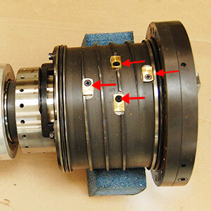
Oil jets, like those on this Mori Seki NH5000, must be removed before the bearings can be taken out. Carefully mark and record where each one goes. They will have to go back in the exact same position. They may be covered with an epoxy sealant to prevent coolant fluid from reaching the bearings.

Oil Mist Lubrication Jets must be removed prior to removing Bearing Stack.
If your spindle has a drawbar, measure and note where and how the springs are assembled. Measure the distance that nuts are on the shaft. And take some more photos.
WARNING! Use extreme caution when removing and handling drawbar assemblies. They are spring loaded and can cause serious injury if not properly handled.
Keep careful track of the way things come off. This is especially true of how things are removed from the spindle shaft. Many components such as bearings have a front and a back and can only go back together in one direction. Also, do not mix up any spacers that may be between the bearings. Although they may look identical, they likely vary by a few microns and they are very specific to their paired mate.
If you find that you need to remove a rotor or a component from the shaft and it does not appear to be threaded, it may be time to stop and consider sending it to a qualified shop. Many motorized spindles have “hydraulic” rotors or hydraulic nuts. DO NOT PRESS THESE OFF. These components have a heavy interference fit that holds them on the shaft. To release them requires pressurizing the interior to about 10,000 PSI and then they come right off. Pressing them off can damage the sealing area and make proper resetting nearly impossible without costly repair.

This Mazak Integrex spindle has a hydraulic rotor and it takes about 10,000 PSI of hydraulic pressure to properly remove it. This rotor must be removed to get to the front bearings.
Caution! Pressing off this type of rotor will damage both the rotor and the shaft.
There is also a process for getting hydraulic rotors and nuts back on.
Keep a separate container for all O-rings and seals that come off of the spindle. We recommend making a replacement kit and matching each old O-ring to a new replacement; one for one. When the spindle is fully assembled there shouldn’t be anything in the kit left over.
Once everything is apart, all of the journals should be carefully cleaned and measured. There are usually four journal areas: front and rear shaft journals and front and rear housing journals. These areas often have multiple journal surfaces. The shaft run-out should also be checked on a set of Vees.
Check all of the shoulders on the shaft and in the housing for any wear or galling. As a minimum carefully stone any high spots flat. If significant deviation is present on the journals consider sending the shaft or housing out for GPG.
At HST all critical surfaces, journals, shoulders and tool interface, are measured to a micron and recorded. Anything out of tolerance is quoted for repair. The DIYer may not have that capability. So he’ll have to live with what he has.
For a more complete discussion of what we do for a spindle repair see our FAQ #4 .
Next you’ll have to get replacement bearings.
Take aways:
- Prepare a place and get ready before you remove the spindle
- Match mark most components before they are removed
- Keep spacer sets together do not mix them up
- Measure gap and handle sensors with care
- Take lots of photos
Please send us your comments, suggestions our questions.
Next week we’ll talk about Angular Contact Bearings, preload and lubrication.
How to Replace Damaged Bearings on a Precision CNC Spindle
We see a lot of forums with questions concerning how to replace bearings on a CNC spindle. So we’ve decided to write a few blog pages that we hope will be helpful for the shops that want or need to DIY. Should you attempt to replace the bearings yourself and along the way you get into trouble or have a question send us an email or call us. We’ll do our best to try to help.
Send us an email at [email protected] or call 1-603-483-0333
We want to provide as much support as possible to shops that may just be starting out or are operating on a shoestring budget. But we want to be very clear that we are not advocating do-it-yourself for spindle repair. Some spindles require very specialized equipment and they can be damaged if not properly disassembled. We know; we’ve damaged a few along our 30 years of spindle repair.
Also, while we endeavor to provide accurate information there is always an exception to just about everything. So look to the spindle or machine manufacturer first. This is a blog series about replacing spindle bearings. It does not cover every detail of spindle rebuilding.
This is the first of a 5 part series where we offer a few tips and cautions concerning bearing replacement for CNC spindles. The information presented here is rather generic and most of it can apply to mills or lathes. If you have a specific question, some hint you’d like to pass along or some criticism please send us an email at [email protected] or call 1-603-483-0333
This week we will offer a few tips on the first part of bearing replacement, taking your spindle apart. Next week we’ll speak about Super Precision Angular Contact Spindle Bearings. We’ll help you get the correct bearings. Then we’ll discuss preload and lubrication.
Topics for upcoming weeks include:
- Week 2 About Angular Contact Bearings and Lubrication
- Week 3 Angular Contact Bearing Installation Arrangement and Preload
- Week 4 About Cylindrical Roller Bearings Installation and Preload
- Week 5 About Capture, Specialty Bearings and Hydraulic Nuts
What You Should Have on Hand
Before you take on a bearing replacement take some time to do a little preparation. Besides the basic tools we recommend that you have the following ready:
- Clean well-lit area
- Lint free paper towels,
- Clean plastic parts bins
- Correct lubricant
- Graduated syringe
- Freezer bags to keep parts in
- Clean dry compressed air (get a can if need be)
- Hot air gun
- Decent digital camera
Depending on your capability we also recommend the following:
- Good digital micrometer capable of sizing the maximum shaft bearing journals.
- Good Vee blocks
- Dial indicator with 1 or 2µm graduation (checking shoulders and run-out)
- Bore gage (micron calibration)
- Johansen Blocks for calibration
- Induction heater for bearing expansion
Most of the second list is only useful if you plan to make corrections to journals that are out of specification. HST will quote GPG for your shaft or housing if needed.
We read blogs where a machine shop just replaces the bearings with new ones. They don’t grind spacers, mess with the capture or touch the journals and all is well (and we believe it). We also know that because of budgetary constraints some shops must do things on their own and they can’t do all of the things that we recommend. So we will try to provide helpful information for a “bare-bones” repair as well as a more advanced repair. If you get into trouble don’t hesitate to give us a call or send an email.
TAKING YOUR SPINDLE APART – Spindle bearing removal
Our first recommendation before you take your spindle apart or even out of the machine is to photograph it from every possible angle. Take plenty of clear pictures along the way as the spindle comes apart. We do. Take notes on a pad. Note how hoses are routed and connected. Improper routing can result in a line failure. Additionally before anything is removed we recommend making “marriage marks” for most things that must go back together. This is especially true of balanced rotating components. Installing them in a different alignment can adversely affect balance.
Carefully mark the position of any sensors. Use non-magnetic shims to measure distances between various sensors and their targets. Many of these have to be set within a small fraction of a millimeter to work properly. Handle all wires carefully. Hard flexing or pulling can result in breaks at solder connections and subsequent control failure. Keep sensors away from magnets and even ferrous metals if possible.
Some spindles use an air/oil mist. These spindles often have nozzles or jets that spray the lubricating mist directly into the bearing race. If that’s the case, carefully note the position of each jet. They may be different sizes and it will be critical to get each one back in its proper place when reassembling the spindle. After they are marked they must be removed before the shaft or the bearings can come out.
Oil jets, like those on this Mori Seki NH5000, must be removed before the bearings can be taken out. Carefully mark and record where each one goes. They will have to go back in the exact same position. They may be covered with an epoxy sealant to prevent coolant fluid from reaching the bearings.
Oil Mist Lubrication Jets must be removed prior to removing Bearing Stack.
If your spindle has a drawbar, measure and note where and how the springs are assembled. Measure the distance that nuts are on the shaft. And take some more photos.
WARNING! Use extreme caution when removing and handling drawbar assemblies. They are spring loaded and can cause serious injury if not properly handled.
Keep careful track of the way things come off. This is especially true of how things are removed from the spindle shaft. Many components such as bearings have a front and a back and can only go back together in one direction. Also, do not mix up any spacers that may be between the bearings. Although they may look identical, they likely vary by a few microns and they are very specific to their paired mate.
If you find that you need to remove a rotor or a component from the shaft and it does not appear to be threaded, it may be time to stop and consider sending it to a qualified shop. Many motorized spindles have “hydraulic” rotors or hydraulic nuts. DO NOT PRESS THESE OFF. These components have a heavy interference fit that holds them on the shaft. To release them requires pressurizing the interior to about 10,000 PSI and then they come right off. Pressing them off can damage the sealing area and make proper resetting nearly impossible without costly repair.
This Mazak Integrex spindle has a hydraulic rotor and it takes about 10,000 PSI of hydraulic pressure to properly remove it. This rotor must be removed to get to the front bearings.
Caution! Pressing off this type of rotor will damage both the rotor and the shaft.
There is also a process for getting hydraulic rotors and nuts back on.
Keep a separate container for all O-rings and seals that come off of the spindle. We recommend making a replacement kit and matching each old O-ring to a new replacement; one for one. When the spindle is fully assembled there shouldn’t be anything in the kit left over.
Once everything is apart, all of the journals should be carefully cleaned and measured. There are usually four journal areas: front and rear shaft journals and front and rear housing journals. These areas often have multiple journal surfaces. The shaft run-out should also be checked on a set of Vees.
Check all of the shoulders on the shaft and in the housing for any wear or galling. As a minimum carefully stone any high spots flat. If significant deviation is present on the journals consider sending the shaft or housing out for GPG.
At HST all critical surfaces, journals, shoulders and tool interface, are measured to a micron and recorded. Anything out of tolerance is quoted for repair. The DIYer may not have that capability. So he’ll have to live with what he has.
For a more complete discussion of what we do for a spindle repair see our FAQ #4 .
Next you’ll have to get replacement bearings.
Take aways:
- Prepare a place and get ready before you remove the spindle
- Match mark most components before they are removed
- Keep spacer sets together do not mix them up
- Measure gap and handle sensors with care
- Take lots of photos
Please send us your comments, suggestions our questions.
Next week we’ll talk about Angular Contact Bearings, preload and lubrication.