Axial Preload for Angular Contact Bearings
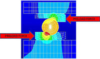
Preload is the load generated from the axial or radial interference within a bearing resulting in elastic deformation between rolling elements and the raceway. In other words, preload is the amount of force exerted against the rolling elements without the application of any external forces. Proper preload maximizes bearing life and optimizes machine performance. Bearing preload influences speed limits, rigidity and other applicable workloads.
If bearing preload is too light the spindle will lose rigidity and might experience ball skip. This can lead to poor part quality and premature failure. Excessive preload can result in excessive heat buildup and premature failure. Getting preload exactly right is a must for proper spindle performance and long life. Achieving proper preload is one of the important skill sets that differentiate a good spindle repair house from a good precision machine shop. It requires a climate controlled environment.
As a general rule roller bearings are preloaded in the radial direction only while angular contact bearings are preloaded in the axial and radial direction.

Radial Preload for Roller Bearings
Radial preload on angular contact bearings is a function of shaft and housing dimensions. At HST we often restore worn or damaged bearing journals to ISO specification. There are several ways to achieve axial preload:Radial Preload for roller bearings can be difficult to set and this is especially true if the spindle uses straight bore roller bearings. The preload for straight bore roller bearings is controlled by shaft and housing interference. Most roller bearings are purchased with a specified radial clearance. For maximum bearing life without sacrificing spindle performance the shaft and housing must be within specification by a very few microns. Obtaining proper preload on tapered bore roller bearings is somewhat easier. The spacers are adjusted by grinding or manufacturing new until the bearing achieves a light preload.
- Rigid Preload
- Constant Pressure or Spring Preload
- Variable Preload
Rigid Preload
Rigid preload is the most common method for most high end CNC machine centers. It involves generating an interference fit between the faces of opposite bearings when bearings are locked axially. Two ways to control the amount of interference (i.e., pre-load) are by a threaded adjustment or precision ground spacers. In either case, these settings can be critical to less than 2 microns (.000078″). Many of the “high-end” spindles such as Okuma, Mori-Seiki, Mazak and Niigata use rigid pre-load. Setting rigid preload requires know-how and skill. Engineering consideration must be given to dimensional changes resulting from thermal expansion and/or contraction. The amount of preload is controlled by the bearing stand-off when angular contact bearings are arranged in a Back-to-Back configuration. Most Super Precision spindle bearings for CNC machines are manufactured for light preload. For this reason spacer sets are ground to exactly the same size. Once spacers are ground to the same dimension the preload will be set when the bearing stack is assembled onto the shaft.
The down side of rigid preload is that the actual preload can vary as a result of thermal expansion. Additionally, the preload can vary when the spindle is operating at very high speeds as a result of centripetal force acting on the balls.

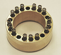
Typical Spring Pack for Constant Pressure Preload
Constant Pressure Preload
Constant Pressure Preload is also called Spring Preload. It is generated by a series of springs reacting against the bearings in the axial direction. Thermal expansion is compensated for by the springs. Bearing preload variations are minimized in this configuration. Care must be given to match the individual springs to avoid uneven loading. This type of preload is common on smaller grinding spindles and is rarely used on mill or lathe spindles.
Variable Preload
Some machines use hydraulic pressure to control the preload. These machines can vary the bearing preload according to the operating speed. This method adds a significant amount of complexity to the design and is rather rare.

Axial Preload for Angular Contact Bearings
Preload is the load generated from the axial or radial interference within a bearing resulting in elastic deformation between rolling elements and the raceway. In other words, preload is the amount of force exerted against the rolling elements without the application of any external forces. Proper preload maximizes bearing life and optimizes machine performance. Bearing preload influences speed limits, rigidity and other applicable workloads.
If bearing preload is too light the spindle will lose rigidity and might experience ball skip. This can lead to poor part quality and premature failure. Excessive preload can result in excessive heat buildup and premature failure. Getting preload exactly right is a must for proper spindle performance and long life. Achieving proper preload is one of the important skill sets that differentiate a good spindle repair house from a good precision machine shop. It requires a climate controlled environment.
As a general rule roller bearings are preloaded in the radial direction only while angular contact bearings are preloaded in the axial and radial direction.

Radial Preload for Roller Bearings
Radial preload on angular contact bearings is a function of shaft and housing dimensions. At HST we often restore worn or damaged bearing journals to ISO specification. There are several ways to achieve axial preload:Radial Preload for roller bearings can be difficult to set and this is especially true if the spindle uses straight bore roller bearings. The preload for straight bore roller bearings is controlled by shaft and housing interference. Most roller bearings are purchased with a specified radial clearance. For maximum bearing life without sacrificing spindle performance the shaft and housing must be within specification by a very few microns. Obtaining proper preload on tapered bore roller bearings is somewhat easier. The spacers are adjusted by grinding or manufacturing new until the bearing achieves a light preload.
- Rigid Preload
- Constant Pressure or Spring Preload
- Variable Preload
Rigid Preload
Rigid preload is the most common method for most high end CNC machine centers. It involves generating an interference fit between the faces of opposite bearings when bearings are locked axially. Two ways to control the amount of interference (i.e., pre-load) are by a threaded adjustment or precision ground spacers. In either case, these settings can be critical to less than 2 microns (.000078″). Many of the “high-end” spindles such as Okuma, Mori-Seiki, Mazak and Niigata use rigid pre-load. Setting rigid preload requires know-how and skill. Engineering consideration must be given to dimensional changes resulting from thermal expansion and/or contraction. The amount of preload is controlled by the bearing stand-off when angular contact bearings are arranged in a Back-to-Back configuration. Most Super Precision spindle bearings for CNC machines are manufactured for light preload. For this reason spacer sets are ground to exactly the same size. Once spacers are ground to the same dimension the preload will be set when the bearing stack is assembled onto the shaft.
The down side of rigid preload is that the actual preload can vary as a result of thermal expansion. Additionally, the preload can vary when the spindle is operating at very high speeds as a result of centripetal force acting on the balls.

Typical Spring Pack for Constant Pressure Preload
Constant Pressure Preload
Constant Pressure Preload is also called Spring Preload. It is generated by a series of springs reacting against the bearings in the axial direction. Thermal expansion is compensated for by the springs. Bearing preload variations are minimized in this configuration. Care must be given to match the individual springs to avoid uneven loading. This type of preload is common on smaller grinding spindles and is rarely used on mill or lathe spindles.
Variable Preload
Some machines use hydraulic pressure to control the preload. These machines can vary the bearing preload according to the operating speed. This method adds a significant amount of complexity to the design and is rather rare.
